I. Main Raw Materials Polyester Polyol (PES): Commonly used with molecular weight Mn≈2000 (hydroxyl value: 53~59 mgKOH/g), melting point: 40~50°C. Common types include: Polyethylene Adipate Diol (PEA), Poly(Diethylene Glycol Adipate) Diol (PDA), Poly(1,4-Butylene Adipate) Diol (PBA), etc. Methylene Diphenyl Diisocyanate (MDI): White or pale yellow crystals at ambient temperature, melting point ~38°C, molecular weight Mn=250. It has poor storage stability at room temperature (prone to self-polymerization). It shall be stored and transported under refrigerated conditions (-5~5°C). It emits an irritating odor when heated; viscosity: 4.9 CPS (at 50°C). 1,4-Butanediol (BDO): Colorless oily liquid, molecular weight Mn=90, specific gravity 1.054, melting point 19.3°C, water content ≤0.1%, hydroxyl value 1230 mgKOH/g. It is highly hygroscopic, soluble in ethanol, acetone, polyether polyols and polyester polyols. If water content is excessively high, desiccants such as calcium oxide or molecular sieves can be used for treatment. After vacuum distillation, the water content can be reduced to below 0.1%. Dichloromethane (CH₂Cl₂): Used as a cleaning agent after casting of CPU products. Colorless volatile liquid with ester-like pungent odor. Soluble in ethanol and esters, slightly soluble in water. Specific gravity 1.34, freezing point -96°C, boiling point 40.1°C. Non-flammable and non-explosive in air, pH value: 6~7. Dioctyl Phthalate (DOP): Used as a circulating pump-sealing agent during startup and shutdown of CPU equipment to prevent seizure of relevant components. Colorless flammable oily liquid, specific gravity 0.98, viscosity 81 CPS (at 20°C). Insoluble in water, miscible with mineral oil. Boiling point 230°C.
II. Process Flow and Operating Procedures 1. Prepolymer Preparation (1) Dehydration of Polyester Polyol: Weigh polyester polyol (PES) and feed it into the degassing kettle through the feeding port. Gradually heat to 100~140°C. (To prevent deterioration of the raw liquid, the heating rate shall not exceed 100°C per half hour.) Under slow stirring (n≈30 rpm) and vacuum of 5~10 mmHg, carry out vacuum degassing for 0.5~1.5 hr until the water content of PES is less than 0.05%, then cool down to 40~60°C. (Part or all of the hot heat transfer oil in the jacket of the degassing kettle is transferred to the hot oil tank, and cold heat transfer oil from the cold oil tank is pumped into the kettle jacket to rapidly cool the raw liquid inside the kettle. For the next production cycle, the warmed cold heat transfer oil is pumped back to the cold oil tank, and cooling water is introduced to cool the heat transfer oil down to 30°C for subsequent cooling use. Hot heat transfer oil is pumped into the jacket to heat PES for the next degassing operation. This method facilitates heating and cooling of the raw liquid and saves energy.) Release vacuum and set aside for later use. (Note: When draining heat transfer oil from the kettle jacket, the electric heater must be shut off to avoid burnout of the electric heating tube due to oil shortage.) (2) Prepolymer Synthesis ① Advantages of the M+P method (adding PES into MDI): The reaction between polyisocyanate and polyol without catalyst needs to be completed at 70~120°C. If one component is in substantial excess, the reaction can proceed at 70~90°C. Therefore, the reaction temperature for prepolymer synthesis is preferably 80±5°C. Gelation readily occurs when NCO:OH = 1. Hence, for the P+M method (adding MDI into PES), improper operation with excessively high reaction temperature will easily cause gelation and scrap the prepolymer. ② Prepolymer Synthesis: Charge a specified quantity of MDI into the synthesis kettle (the filling volume generally should not exceed 75% of the total kettle volume). Heat to 40~50°C. Under medium-speed stirring (n=60~80 rpm), gradually add dehydrated PES as required by the formula. The reaction is exothermic and the temperature will rise naturally. After 30~40 min, maintain the temperature at 80±5°C with auxiliary heating and hold for 1~3 hr. (If necessary, partially introduce cold heat transfer oil into the jacket of the synthesis kettle to control material temperature.) Continue the reaction until the NCO value meets specifications. Then perform vacuum defoaming (2~10 mmHg, 1 mmHg=133 Pa) under slow stirring for 10~40 min. The material is ready for casting. (Transfer to the A-component tank of the CPU pouring machine by pump or vacuum suction.) ③ Feeding method for polyester polyol: Adjust the rotation speed (flow rate) of the MDI metering pump according to reaction requirements to stabilize the reaction process and facilitate temperature control. The synthesized prepolymer features low free isocyanate monomer content and a relatively regular structure. To guarantee prepolymer quality, PES dehydration and prepolymer synthesis are preferably carried out in separate kettles under dry nitrogen protection. Strict temperature control and cooling measures are required to prevent violent reactions. (Practice shows that prepolymers produced at lower temperature have lower viscosity and better processability plus superior physical properties of final products. However, reaction at low temperature without catalyst extends reaction time, which is unfavorable for production.)
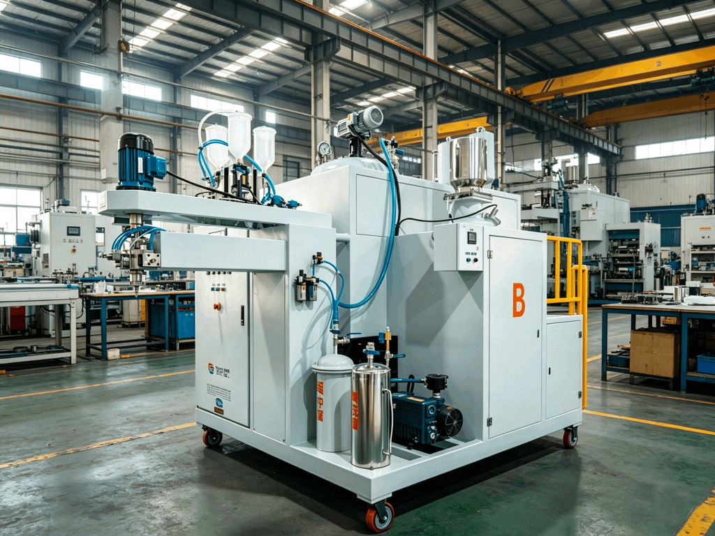
2. Casting via Pouring Machine Load the prepolymer into the A-component tank, and the cross-linking agent (BDO) into the B-component tank. (If pigments or other additives are required, mix them thoroughly before feeding.) Circulate the A and B raw liquids separately. Vacuum degassing shall be performed if necessary: not only the prepolymer requires rigorous degassing, but BDO also needs vacuum degassing due to its high hygroscopicity. Bring both streams to the specified temperature. Adjust the mixing ratio as per the formula requirements (i.e., set the rotation speeds of A and B metering pumps, and balance the casting pressure and return pressure). Press the casting button. Once A and B components are uniformly mixed in the mixing chamber and no bubbles appear in the discharged transparent hose, casting can start. Molds shall be coated with release agent and preheated to the required temperature (the temperature difference from the casting material shall not exceed 10°C). Select an appropriate casting method (such as centrifugal casting, vacuum casting or suitable atmospheric casting) to avoid bubble formation. If the interval between two casting operations exceeds one-third of the pot life, the mixing chamber must be automatically cleaned with cleaning solution (dichloromethane) under the control of the programmable controller. The mixing head and mixing chamber must be thoroughly cleaned and blow-dried; no cleaning residue is allowed. When casting stops, A and B raw liquids automatically switch to recirculation and return to their respective tanks in laminar flow. Return pipelines are typically designed at the bottom of the tanks to prevent bubble generation inside the tanks caused by material flow impact.
3. Curing The curing conditions for CPU products are divided into three stages: (1) Mould Curing: It refers to the curing process of the product inside the mould before demoulding. The temperature should be as high as possible on the premise that no thermal decomposition occurs to the chemical structure of the product, so as to accelerate chain extension and cross-linking reactions, shorten the demoulding cycle and improve the utilization rate of moulds and equipment. The recommended condition is 100~120°C with a demoulding time of 10~50 min. The target is to obtain sufficient demoulding strength and prevent permanent deformation upon demoulding. (2) Post-Curing: Continuous thermal curing after demoulding. The recommended condition is 90~110°C for 10~40 hours to complete the reaction of -NCO groups. The temperature and duration depend on the product thickness and raw material formulation. (3) Post-Aging: Store the product at room temperature or slightly elevated temperature for one week to optimize the physical structure and mechanical properties of the finished part. Product application or physical property testing shall be carried out only after post-aging.
III. Troubleshooting During Operation or Commissioning 1. How to Ensure Metering Accuracy (1) The CPU pouring machine has two metering accuracy requirements: ① Metering requirement for mixing ratio: Variation of mixing ratio will directly affect the quality and physical properties of finished products. ② Metering requirement for casting material: Fluctuation in the total output of the pouring machine only changes the casting duration. For non-foaming casting materials, the casting volume has basically no impact on product quality. (2) Factors affecting metering accuracy: ① System process design: Pouring machines requiring high-precision metering generally adopt the “full pouring – recirculation” process. ② Accuracy of metering pump assembly: metering accuracy of the two-component metering pumps; precision and stability of pump speed regulators and display instruments. ③ Adequate, stable and smooth feeding of the material supply system. (The resistance of the pre-pump filter and the viscosity of raw liquid shall not be excessively high.) ④ Reasonable structure of mixing, pouring and recirculation system with stable and reliable resistance and pressure. Synchronization of the pouring switching device when two components enter the mixing chamber, and balance between recirculation pressure and pouring pressure. ⑤ Skilled operation and adjustment in accordance with process requirements. (3) Test methods for metering accuracy: (DOP simulation test or actual raw liquid test can be adopted.) ① Stabilize test conditions: Keep basic parameters such as material temperature, pressure and flow rate (i.e., rotation speed and ratio of metering pumps) as consistent as possible with practical operating requirements. True metering error can only be reflected when basic conditions remain unchanged. ② The casting duration during measurement shall not be too short; several minutes of casting is preferred. Especially when testing low total output or high mixing ratio, the flow rate of component B is very low. Too short casting time during measurement may lead to significant errors. Errors caused by improper measurement must be eliminated. ③ Adjustment method: When adjusting the mixing ratio according to formula requirements, fix the rotation speed of component B (small pump, constant flow rate) and adjust the rotation speed of component A (large pump). This can improve the metering accuracy of mixing ratio. ④ Keep a close watch on the rotation speed of metering pumps during metering accuracy measurement. Flow rate measurement can only be carried out when the rotation speeds of both metering pumps remain constant. Otherwise, rotation speed may drift due to changes in voltage, current, system pressure, material temperature and other factors. Identify the root cause of speed fluctuation, troubleshoot and stabilize pump speed before conducting metering accuracy testing.
2. How to Ensure Uniform Mixing of Each Component For two raw liquid components with large differences in viscosity and mixing ratio, uniform mixing must be achieved within an extremely short time by high-speed stirring in the mixing chamber of the pouring head without bubble generation. The following measures shall be adopted: (1) The opening/closing switching mechanism for each component shall operate flexibly and synchronously. Each raw liquid component enters the mixing chamber in an injection state at a specified velocity (i.e., with a defined pouring pressure). This prevents deviation of the preset mixing ratio caused by viscosity and pressure differences between the two components. Orifice plates and throttle valves are used to adjust pouring pressure to ensure neither component leads nor lags as they enter the mixing chamber. Pneumatic mechanisms deliver fast response and flexible switching; however, the compressed air pressure must not be too low (>0.4 MPa), otherwise normal switching performance will be impaired. (2) Structure and type of mixing head, stirring speed and power: Mixing heads for CPU mostly adopt straight-flow stirring. The mixed material has no vertical movement during stirring and mixing to avoid bubble formation. Well-designed conical or straight mixing heads available today can achieve thorough mixing without bubbles. Select the appropriate stirring speed according to the pouring output, mixing ratio and raw material viscosity. (3) Tightness of the mixing system. The airtightness of static parts can be ensured by proper gaskets during assembly. Special attention shall be paid to sealing requirements for dynamic parts during commissioning and operation, mainly including: the stirring shaft, cleaning and air purge switches, rotating shafts for switching, and the adjusting shaft of the recirculation regulating valve. Adjust or replace these components appropriately according to their sealing structure and material requirements. (4) Residence time of mixed material inside the mixing chamber can be adjusted by the outlet bore diameter of the pouring head, the clearance between mixing head and mixing sleeve, and the total pouring output (g/s) during casting.
3. Main Factors Affecting System Temperature and Control Accuracy (1) Correct system configuration and reasonable process flow: A fully forced-circulation heating system using heat transfer oil is adopted. The heat transfer oil is heated by oil-immersed tubular electric heaters, featuring stable temperature, convenient operation, sensitive control and long service life. (Electric heating rods were tested previously but are seldom used due to local overheating and short service life.) (2) Heating method, capacity and layout of electric heaters: The pouring machine adopts two-stage heating for material tanks and oil tanks. Both stages heat simultaneously during startup to reach the target temperature rapidly. Once the target temperature is achieved, the higher-power heater for the material tank automatically shuts down. The electric heater inside the oil tank performs intermittent heating to maintain temperature steadily near the set value, improving temperature control accuracy and saving energy. Electric heaters are generally oversized in design to prevent insufficient heating capacity. (3) Temperature control method, control instruments and probe position: Intelligent time-proportional (PID) temperature controllers and Pt100 platinum resistance sensors are used. The proportional band can be adjusted if needed to meet temperature control requirements. (Temperature fluctuation may be large at the initial stage. After a period of time, all process parameters stabilize, temperature variation diminishes and the target temperature is attained.) 4. How to Ensure Macro Bubble-Free Products No visible bubbles to the naked eye is one of the critical quality indicators for CPU products. (1) Potential causes of bubbles in elastomer products: ① Adsorbed gas entrained in raw materials, foaming components contained in raw materials, and gas generated by reaction due to excessive moisture in active-hydrogen-containing components; ② Bubbles generated during raw material mixing (caused by unreasonable structure of mixing head or mixing chamber, mismatch between pouring output and mixing head size, etc.); ③ Bubbles entrapped during liquid injection into the mould. Contributing factors include unreasonable mould design, poor venting, excessively low mould temperature or dirty mould surface, improper timing for mould clamping and pressurization, and failure to crush and eliminate surface bubbles. (2) Key considerations: ① The prepolymer shall be thoroughly defoamed to eliminate bubbles. Check whether the vacuum system leaks and whether the temperature of Component A facilitates defoaming. This can be verified by pouring Component A along the wall into a glass ring while measuring flow rate and mixing ratio. Monitor the water content of the curing agent component; dehydrate or bake it before use if necessary. ② No bubbles shall form while components mix inside the pouring head, which depends on the mixing head configuration and sealing condition of the pouring system. Select a mixing head (with proper cavity volume) and discharge funnel (suitable outlet diameter) matched with pouring output and raw material viscosity to avoid bubble generation during mixing. ③ No bubbles shall form when mixed material is poured into the mould, determined by pouring method (atmospheric pouring, pressure-clamping pouring, vacuum pouring and centrifugal pouring), mould structure and feeding mode (edge feeding, discharge rate, etc.). Avoid excessively long hoses connected to the pouring head. The liquid shall flow in laminar fashion along the mould edge during injection to prevent bubble entrapment. ④ If pressure-clamping pouring is adopted, proper mould-clamping timing must be controlled. ⑤ Design moulds rationally to ensure smooth venting and maintain appropriate mould temperature. ⑥ Clean moulds carefully and apply release agent evenly to prevent accumulation.
 FEILONG PU MACHINE