一 For certain imported equipment and components, φ4~5 polyurethane sealing rings need to be cast into the plastic frame groove of filters. The sealing rings shall have a smooth and even surface, good elasticity and strong adhesion to the groove of the plastic frame. Through continuous testing and improvement, we have successfully developed the corresponding process and equipment. Small-batch trial products have been approved by relevant international customers. 二. How to Meet Product Requirements (Raw Material, Machine, Mold, Operation) 2.1 Qualified raw materials and suitable process (1) Raw Materials Self-skinning (ISF) polyurethane foam with proper strength and smooth surface shall be adopted. Main parameters of self-skinning formulation: ① A two-component system is commonly used. Material temperature: 22±2℃; mold temperature: 35~40℃; mixing ratio A:B ≈ 100: 35~40 Component A: Hydroxyl value (mgKOH/g): 145~172; Viscosity (20℃, mPa·s): 600~1000; Density (20℃): 1.05 Component B: -NCO content (%): 28±1; Viscosity (25℃, mPa·s): 150~300; Density (25℃): 1.22 ② Reactivity: Cream Time (CT): 20~30 s; Rise Time (RT): 50~60 s Gel Time (GT): 40~50 s; Demold Time (DMT): 180~300 s ③ Physical properties: Bulk density (kg/m³): 200~600; Tear strength (N/m): 1700~2100 Tensile strength (MPa): 0.7~2; Hardness (Shore A): 30~70 Elongation at break (%): 100~200; 50% Compression set (%): <4.5 (2) Process An ultra-micro foaming machine is used to dispense the polyurethane mixture into the semicircular groove of the mold pre-sprayed with release agent, at a discharge rate of 0.5~1 g/s and traverse speed of 100~200 mm/s. The plastic filter frame is positioned by a locating fixture for accurate alignment with the mold. After heating to 50~60 ℃ and curing for 3~4 minutes, the mixture foams and bonds inside the groove of the plastic frame. The finished part is obtained after demolding and trimming. Process requirements: ① Water content in raw materials must be strictly controlled for self-skinning foaming. Water reacts with NCO groups to generate CO₂, which cannot remain as liquid in the foaming system and will disrupt skin formation. Normally, the water content in polyol shall be less than 0.01%. ② Overfilling of the mold is required to achieve a certain skin thickness (typically 20–40% overfill). Increasing blowing agent loading raises skin density. For thin-skin products, reduce blowing agent dosage or increase mold temperature for adjustment. Partially replacing F-11 (b.p. 23.7℃) with high-boiling-point blowing agent methylene chloride (b.p. 39.8℃) can noticeably increase skin thickness. To optimize cell structure and raise open-cell content, a small quantity of air can be introduced in a controlled manner for nucleation. ③ Mold temperature shall be strictly controlled according to raw materials, process and mold design.
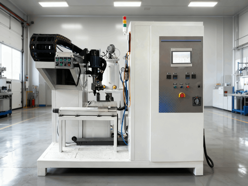
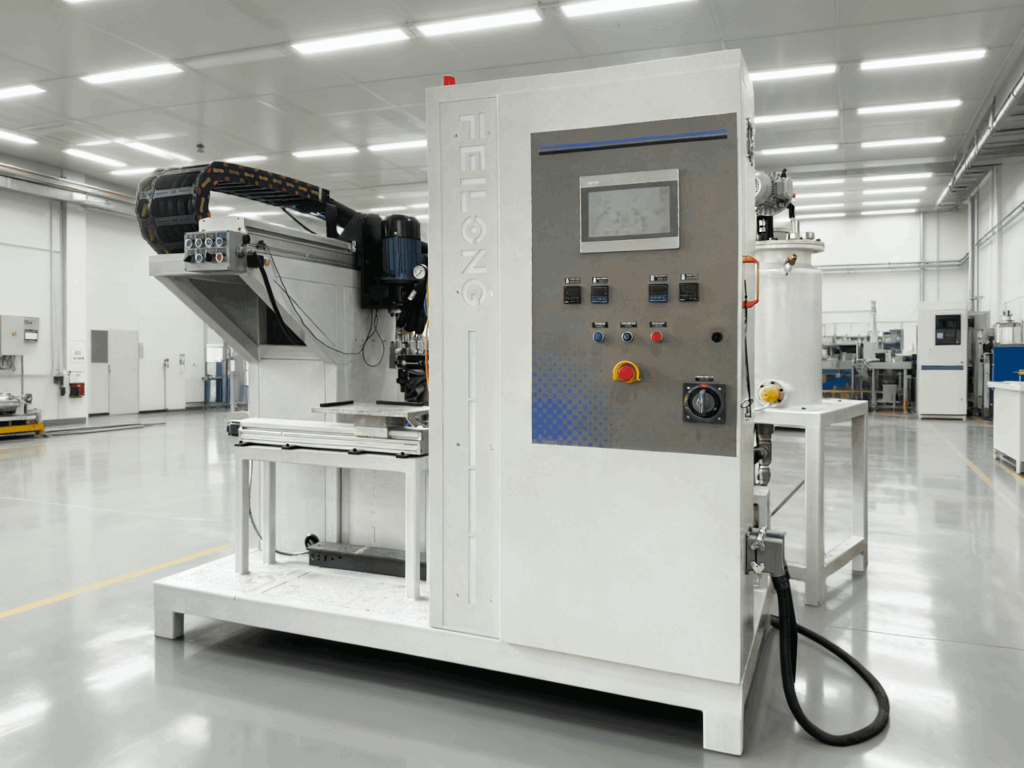
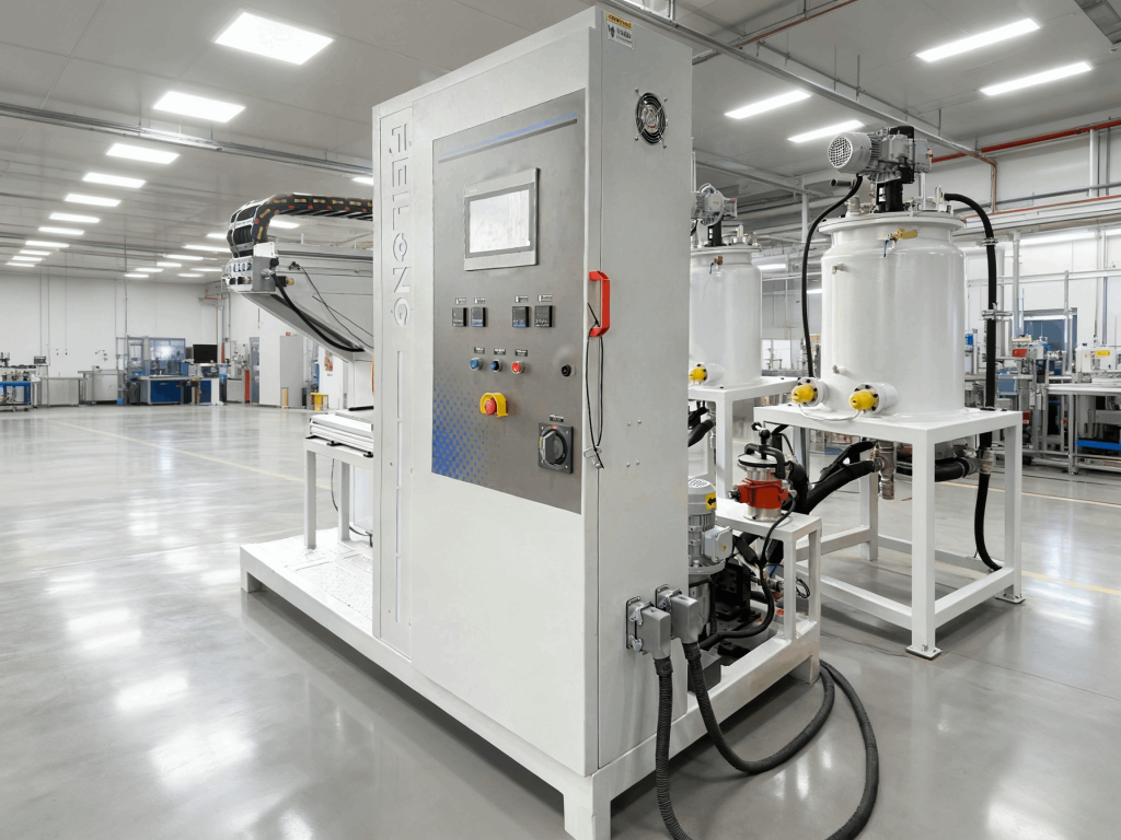
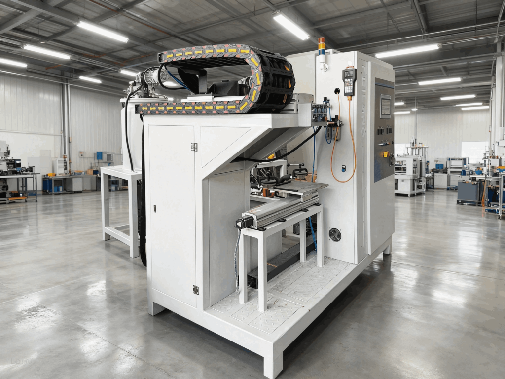
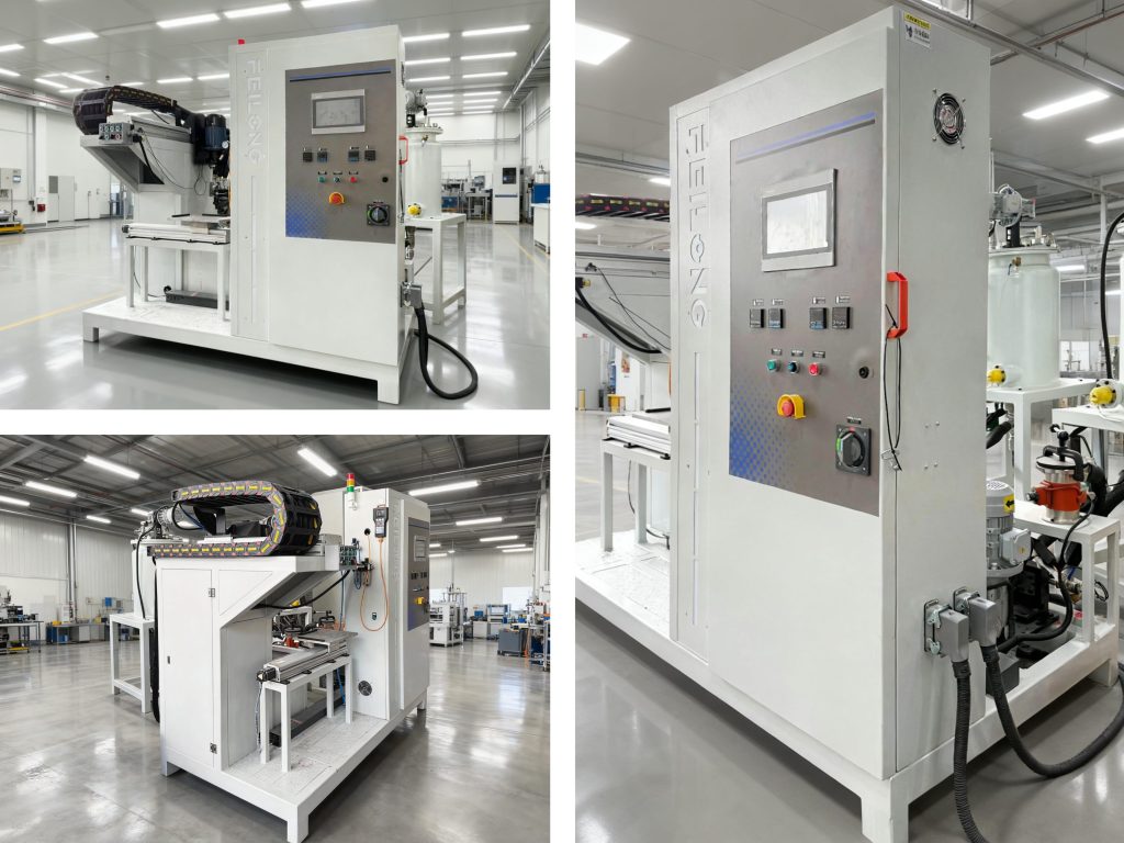
2.2 High-performance ultra-micro foaming machine The sealing strip is fine (approx. φ4~5), with a weight of roughly 0.25~0.4 g per 100 mm length (calculated at density of 200 kg/m³). Main required parameters of the foaming machine: Total output: 0.2~1 g/s; Design mixing ratio A:B ≈ 100:40 (1) Material tank: Volume V=10 L (φ200 × 300), identical specification for A and B tanks (2) Metering pumps: High-precision metering pumps Pump A output: 0.2~1 g/s; Power: 0.37 kW Pump B output: 0.08~0.4 g/s; Power: 0.37 kW (3) Pouring head: Stirring power 0.37 kW (variable frequency speed control, 3000~6000 rpm) (4) Digital automatic control for temperature, metering, pressure and pouring output The foaming machine is critical to yield stability: it accurately meters the two temperature-conditioned components per formulation, mixes them homogeneously and dispenses a fixed shot volume into the mold. 2.3 Mold Hardened aluminum alloy is widely used for lightweight handling and smooth surface finish. The mold shall facilitate free flow of the casting compound and venting of surface bubbles, and enable fast mold closing and clamping. 2.4 Correct operating procedure Select a suitable pouring process matched to different molds; rapidly analyze and resolve abnormalities when faults occur. 三. Three Process Configurations of Micro Foaming Machines 1.High-pressure machine: Adopts high-pressure metering (15–25 MPa), impingement mixing and high-pressure pushrod self-cleaning pouring head (no solvent cleaning of mixing chamber after each shot). Micro foaming machines feature very low total pouring output (<12 g/s) and a large difference in mixing ratio and viscosity between the two components. To achieve high-pressure impingement mixing, the material jet entering the mixing chamber must exceed 150 m/s, which requires extremely small orifices (d<0.5 mm). Such tiny holes are prone to clogging and unstable production. Therefore, micro high-pressure foaming machines are not available either domestically or internationally. 2.High-speed machine: Adopts medium-pressure metering and high-speed screw mixing (n>15000 rpm). A high-speed conical screw scrapes the mixing chamber for self-cleaning (no solvent cleaning). It delivers high automation (e.g. European high-speed models). However, the structure is complex, demanding premium materials and ultra-high machining precision, together with highly skilled operators and maintenance technicians. Given the current domestic foundational industry level (material, heat treatment and machining accuracy), mass production of such high-precision equipment with long-term reliable service life remains difficult. 3.Low-pressure machine: Adopts low-pressure high-precision metering pumps and mechanical agitation mixing with automatic solvent cleaning. It supports precise metering at low flow rates, and performs especially well when the two components differ greatly in viscosity or mixing ratio. This configuration is most suitable for micro foaming machines.
四. Key Modules 4.1 Metering Module 1.Factors affecting metering accuracy (1) Balanced feeding and proper filtration: Raw material viscosity varies with temperature. Within allowable process limits, moderately raising material temperature reduces viscosity for smoother feeding. If raw material viscosity is excessively high (>2000 cP), nitrogen pressure below 0.03 MPa can be applied to the tank to deliver steady feed to the metering pumps. (2) Metering pump: Construction and precision of drive assembly and speed display. Equipped with low-speed high-precision metering pumps, precision infinitely variable transmission and digital tachometer, the error can be controlled below 0.5% under correct operation. (3) Stable flow resistance of feed and recirculation circuit, sensitive pressure regulation. Note: Premium polyurethane equipment uses the full recirculation – pour circuit rather than the straight-through circuit. Straight-through circuit: Filtered A and B materials from tanks are delivered by metering pumps to the mixing unit and poured after uniform mixing. Advantages: Simple layout without recirculation lines; used for low-spec applications such as PU rigid foam spraying. Full recirculation – pour circuit: A and B materials are pumped to the mixing unit and controlled by a synchronous switching valve. During pouring, all A and B flow into the mixing chamber and are homogenized by high-speed stirring of the mixing head for dispensing. When pouring stops, feed to the mixing chamber is cut off and all material returns to its original tank. By adjusting feed pressure and recirculation pressure, the mixing ratio stays constant throughout the shot. This eliminates ratio drift at the start or end of pouring which causes defective parts, and greatly improves the qualified rate. 2.Metering pump configuration and main parameters: Design mixing ratio: Flexible foam (R) A:B = 3:1; Rigid foam (Y) A:B = 1:1 3.Metering pump speed calculation Based on the required output, look up the displacement per rpm of this micro metering pump and calculate the pump speed. Example: PU20F-WR2 micro foaming machine Pump A displacement: 6 cc/rpm; Pump B displacement: 1.2 cc/rpm Specific gravity of A: 1.05; Specific gravity of B: 1.21; Weight mixing ratio 100:35. Set the speed according to calculation for commissioning, measure the actual output of Pump A and B, then fine-tune to meet the target mixing ratio. (For flow calibration, adjust the recirculation regulating valve and throttle plate orifice size to balance pouring pressure and recirculation pressure). If the mixing ratio measured at 0.3 s and 3 s is consistent, initial-shot and end-shot ratio deviation will be eliminated for the entire pouring cycle.
4.2 Mixing Assembly (Pouring Head) 1.Pouring – recirculation switching unit A three-position cylinder synchronously actuates the rotary valve shafts for both components via rack and pinion: Rack at top position: A and B rotary valves set for air purge / cleaning; A and B material under recirculation. Rack at middle position: A and B material under recirculation; cleaning and air purge closed (cleaning orifice never clogs). Rack at bottom position: cleaning and air purge closed; A and B material set for pouring. During pouring, A and B streams enter the mixing chamber through small holes in the throttle plate. During recirculation, material flows back to the respective tanks via recirculation regulating valves. (Recirculated material returns to the tank from the bottom to avoid bubble formation and stabilize material temperature). 2.Pressure regulating unit Recirculation regulating valves fitted on both sides of the pouring head deliver fine adjustment of recirculation pressure (sensitive, reliable fine tuning, anti-clogging). Pouring pressure is adjusted by the bore diameter of the throttle plate. 3.Stirring drive and shaft end sealing A 0.75 kW 2-pole motor drives via V-belt stepped pulley, providing two stirring speeds: 4500 rpm and 5000 rpm (speed display fitted). High-precision imported bearings are adopted. Precision oil seals and special shaft seals are installed to prevent backflow of mixed material upward. (Operating note: Replace the funnel promptly if its outlet is narrowed by cured material, otherwise excessive pressure inside the mixing chamber will push material backward). Cleaning unit The mixing chamber must remain clean after each batch (airtight, no residual cleaning solvent) to guarantee trouble-free operation of the next cycle. The PLC controls solenoid valves for automatic air purge or solvent cleaning, and effectively prevents raw material from flowing back into the cleaning pipeline. Mixing head Specially designed high-shear mixing head: simple, practical, provides homogeneous mixing, no pressure fluctuation during intermittent pouring, and is easy to clean. Changing the outlet aperture of the funnel adjusts the residence time of the mixture inside the mixing chamber.
4.3 Control & Display System 1.PLC controller (Stable performance, robust structure, user-friendly and easy to learn) (1) Automatic control and display of shot volume; supports independent or identical shot volume settings for up to 99 stations (pouring time: 0.10 ~ 99.9 s). (2) Brake control for intermittent pouring: To prevent dripping after each mold shot, when pouring stops, the rotary valve rack returns to the middle position (material recirculation, cleaning closed). The mixing head motor stops and brakes at the same time. (3) Automatic air purge and solvent cleaning control: If the pause after a batch exceeds 2/3 of the cream time, the automatic cleaning sequence activates: Air purge → solvent wash → Air purge (mixing head rotating at high speed) → Air purge (mixing head stopped). Adjust the duration of each step to fully clean and dry the mixing chamber. 2.Temperature control system Stable material temperature is essential for consistent production. Normal material temperature range: 18~24 ℃. For winter startup, electric heating tubes at the tank bottom can preheat raw material temporarily. After stable production, switch off the heater circuit breaker and circulate cooling water through the tank jacket (corrosion inhibitor is recommended). The tank is of three-layer construction with external PU rigid foam thermal insulation to stop condensation on the tank exterior when cooling water is applied in summer. Material temperature is automatically controlled by a digital temperature controller. 3.Raw material pressure display High-precision digital pressure gauge and diaphragm pressure sensor, display accuracy up to 0.01 MPa. 4.Flow rate (metering pump speed) display High-precision tachometer shows pump speed for calculation or on-site testing of pump flow and mixing ratio. 5.Pouring head stirring speed display Used to identify the optimal operating speed and monitor normal running of the mixing head.
 FEILONG PU MACHINE