Search the whole station
Wenzhou Feilong Polyurethane Equipment Engineering Co., Ltd.
Chinese website: http://www.pumcn.com/
English website: https://www.flpumachine.com/
In production and daily‑life scenarios, a large number of fluids need to be transported through insulated or refrigerated pipelines. Traditional thermal‑insulation materials such as glass fiber, asbestos, slag wool, perlite, sawdust and asphalt have many drawbacks. Their construction procedures are complicated and inconvenient. Some materials are harmful to construction workers, featuring high thermal conductivity, poor thermal‑insulation performance, large energy loss and short service life. Rigid polyurethane foam is an ideal thermal‑insulation material for pipelines.
1 Comparison of Thermal‑Insulation Performance Between Rigid PU Foam and Other Materials
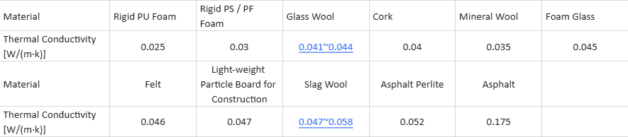
2 Required Thickness of Different Materials for Equivalent Thermal‑Insulation Effect

3 Comparison of Thermal‑Insulation Materials for Oil‑Field Oil‑Transport Pipelines

4. Main Advantages of Rigid PU Foam Used as Pipeline Thermal‑Insulation Material
(1)Excellent thermal‑insulation performance; thin and light insulation layer.
(2) Suitable for large‑scale factory production with high output and stable quality.
(3)Good chemical resistance; it delivers heat‑preservation performance as well as favorable anti‑corrosion properties.
(4)Dense outer surface of foam, low water permeability, long service life (more than 20 years).
(5)Simple and convenient production & construction, high efficiency, safe and reliable.
5 Main Performance Requirements for Rigid Foam for Pipeline Insulation
(1)Technical Standard for Anticorrosion & ThermalInsulation Layers of Rigid Polyurethane Foam for Buried Steel Pipelines (Petroleum Industry Standard SY/T041596)
Apparent density 40~60 kg/m³
Compressive strength ≥0.20 MPa
Water absorption (soaked in water at 23 ℃ for 96 h) ≤0.03 g/cm³
Thermal conductivity ≤0.03 W/(m·k)
Heat resistance (oventreated at 130 ℃ for 96 h)
Dimensional change ≤3%
Weight change ≤2%
(2)Prefabricated Directburied Insulation Pipe with HDPE Outer Casing and Polyurethane Foam Plastic (Urbanconstruction Industry Standard CJ/T1142000)
Apparent density 60~80 kg/m³
Compressive strength (10 % deformation) ≥0.3 MPa
Water absorption (boilingwater soaking for 90 min) ≤10 %
Thermal conductivity (50 ℃) ≤0.033 W/(m·k)
Closedcell ratio >88 %
1. Manual or mechanical mould foaming
Steel pipes of different diameters adopt matched moulds for foaming. Pipes can be placed vertically, horizontally or inclined. Mould length is generally 1‑2 m. Each pouring produces an insulation shell of only 1‑2 m. Segmented insulation layers are applied to pipes, followed by FRP outer protective layers. This process suffers material waste, low efficiency and poor quality and is rarely used nowadays.
2. One‑step continuous industrial production
Steel pipes are conveyed forward on a conveyor belt. The rigid‑foam insulation layer and HDPE protective jacket are formed simultaneously. This process features high automation and high productivity (typically up to 3 m/min). However, it requires high one‑time equipment investment and high technical competence. Large‑diameter pipes consume large material volumes and slow down extrusion. Thus it cannot produce large‑size pipes and may cause eccentricity between steel pipe and insulation layer. It is seldom adopted by medium‑ and small‑scale manufacturers.
3. Two‑step industrial production (suitable for all pipe diameters, especially large‑diameter pipes)
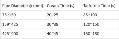
Pre‑fabricate (or purchase) outer protective jackets. Fit them onto steel pipes via centering spider spacers, then pour polyurethane mixture into the annulus for foam forming. High flowability of the mixture is required to achieve uniform foam density. Reaction‑property requirements for the polyol‑isocyanate system are shown below:
1. High‑pressure machine: High‑pressure pumps meter raw materials. Two liquid streams collide at high speed (>150 m/s). A precision‑fitted high‑pressure push rod cleans the mixing chamber. Benefiting from high‑pressure impingement mixing and self‑cleaning pouring head, the pouring head is compact (no mixing motor required). No solvent cleaning is needed after pouring (cleaned by high‑pressure push‑rod scraping). It suits production with long intermittent intervals between pours (e.g. refrigerator manufacturing). High‑pressure machines have complex structures, high investment and high requirements for operation and maintenance. They are not suitable for very small shot sizes or feedstock pairs with large viscosity / mixing‑ratio differences.
2. Low‑pressure machine: Low‑pressure metering plus mechanical stirring mixing; solvent cleaning for mixing chamber. Advantages: simple structure, easy operation and low investment. It adapts to feedstock of various viscosities and mixing ratios with wide adjustment range. It is especially suitable for batch production where dozens of articles are poured before a long pause (cleaning is needed only after dozens of shots).
3. Comparison between the two machine types: Reliable high‑pressure machines are currently imported units or domestically‑assembled machines with imported components. As a developing country, China faces “unaffordable purchase and high running‑cost” issues. High one‑time investment plus expensive long‑term maintenance make it hard for end‑users to achieve sound economic returns. Constrained by domestic industrial foundation, especially in material science, heat treatment and precision machining, domestically‑imitated high‑pressure machines are only “similar in appearance” rather than “equivalent in performance”. There are obvious gaps in process performance, technical indicators and service life compared with genuine imported machines.
4. Configuration of key assemblies (tank, pump, head, control) for two common types of low‑pressure rigid‑foam moulding machines.
5. Brief introduction to key assemblies of high‑pressure machines:
a.Tank: To boost inlet pressure for high‑pressure metering pumps and overcome resistance from sheet filters, high‑pressure‑machine tanks must be pressure vessels (0.1‑0.3 MPa). Their design, manufacture and operation must comply with certified national standards.
b. Pump: Seven‑plunger high‑pressure variable‑displacement pump (10‑20 MPa). Flow rate and mixing ratio can be adjusted at constant motor speed. Complex structure and high precision; domestic products are not yet mature.
c. Head: High‑pressure self‑cleaning pouring head with sophisticated structure, not yet fully localized in China. A dedicated high‑pressure hydraulic station is mandatory, which increases system complexity and investment.
d. Control: Electrical and instrument control system is far more complex than that of low‑pressure machines.
Our large‑flow rigid‑foam foaming machine PU20F‑Y is recommended.
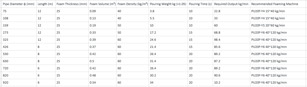
 FEILONG PU MACHINE